close
Choose Your Site
Global
Social Media
Views: 0 Author: Site Editor Publish Time: 2026-08-04 Origin: Site


Industrial plants need exact ways to make real parts. You choose between old ink systems and new additive manufacturing. Old ways put ink on surfaces with plates or screens. Additive systems stack raw materials layer by layer. They build solid 3D things.
Core Selection Parameters: Engineers pick the best way by checking dimensional accuracy, surface roughness, throughput, and isotropic material properties.
Dimensional accuracy checks exact part sizes. Surface roughness shows texture quality. Throughput tracks full production speed. Isotropic material properties give equal strength everywhere. You judge Printing Technologies well by checking these key measures against your part costs and strength needs.
Table of Contents
Old printing tools save money on huge jobs.
3D printers make tricky custom items from files.
Techs pick methods by checking size and strength.
Plastic filaments and liquid resins make detailed parts.
Metal printing makes tough parts for space planes.
Post-processing steps smooth rough spots and fix stress.
Additive manufacturing helps shops make small batches easily.
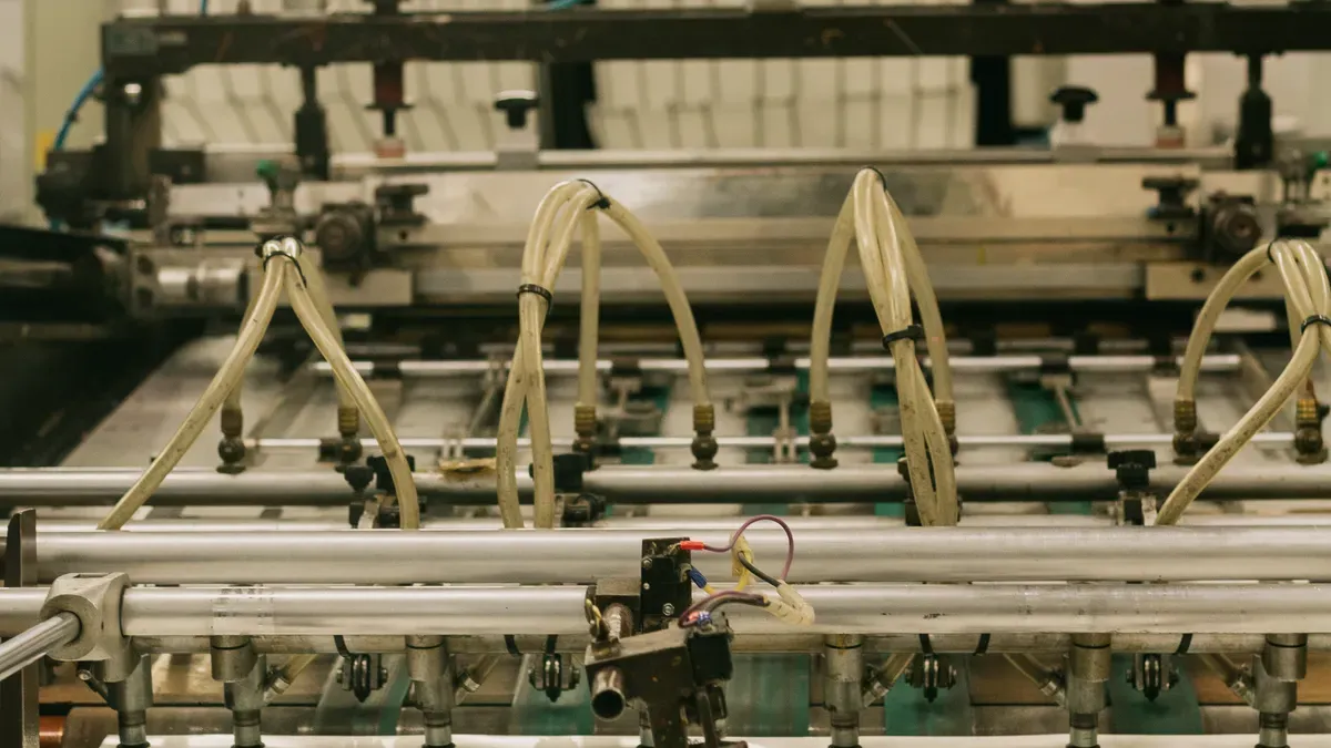
Old factory methods split picture parts and blank parts. They use different surface shapes to do this. You can find four main shapes here. They are flat, raised, sunken, or holey surfaces. These old ways make matching copies very fast. Big factory runs cut your single item costs. They cost much less than 3D printing.
Offset lithography uses a flat top shape. Plant experts name this idea planography. Oil and water push away from each other. You use this trick instead of high walls. You treat metal plates with safe chemicals. This step makes picture spots hold oil ink. Blank spots hold water and push ink away. You roll ink onto a soft cylinder first. Next, the soft cylinder rolls ink on paper.
You put paper into machines as single sheets. You can also use long paper rolls. Sheet machines print flat paper, card boxes, and boards. Web machines print paper rolls at super fast speeds.
Press Category | Operational Benchmark | Maximum Speed Rate |
|---|---|---|
Sheetfed Offset | Standard production range | |
Flagship Sheetfed | Advanced commercial standard | |
Web Offset | Linear continuous web speed | 3,000 feet per minute |
Web Offset | Cut-off production rate | Up to 80,000 cut-offs per hour |
Flexography uses raised top shapes on parts. You stick bendy rubber plates onto spinning tubes. A hard ceramic roller moves set ink amounts. It sends ink to the high plate spots. Teeny holes cover the hard roller surface. These small holes hold exact ink amounts. The plate takes ink from the roller. Then it stamps ink right on your stuff.
ℹ️ Fast-Drying Ink Transfer: Flexography uses thin, fast-drying inks. You print stacked color coats with no mess.
Flexo tools print on nearly any item. Bendy plates fit rough items with ease. You can print on box boards and plastics. You can also print on foils and stickers. Fast flexo printing leads the huge box market.
Gravure printing uses sunken top shapes. You cut millions of teeny holes into steel. These heavy steel tubes have thin metal coats. A flat doctor blade scrapes extra ink away. Ink stays inside the tiny cut holes only. Your paper goes between two heavy spinning tubes. A soft tube presses paper deep into holes. This action pulls out all the wet ink.
Gravure tubes give great strong life. Metal coats shield the tiny holes from wear. This shield lasts over millions of non-stop prints. You make bright pictures with deep ink coats. You also get rich full color mixes. Big book shops and box makers pick gravure. These traditional printing technologies run well for long times.
Screen systems use open shapes. You pull fine mesh tight. A metal frame holds it. Strong plastic or steel wire works. Soft light-sensitive liquid coats it. Light blocks the plain spots. Water washes the open holes clean.
You put substrate right under it. Next, pour thick ink on top. A rubber blade presses down hard.
Squeegee Dynamics: You balance blade pressure and speed. Good control keeps edges sharp.
The blade pushes ink through holes. The mesh touches paper fast. Then, it snaps back up quickly. This step leaves crisp ink marks.
Screen systems print super thick ink. You print on thin glass plates. Ceramic, plastic, and cloth work too.
Factories build electronic parts now. You print silver circuits easily. Carbon lines and insulator coats work. Solar makers print silver lines fast.
Parameter | Operational Range |
|---|---|
Material Viscosity | 1,000 cP to > 1,000,000 cP |
Layer Thickness | 10 µm to 35 µm |
Screen tools print dense paste well. Normal machines hate thick liquid. Screen tools like heavy stuff. Open holes stay clean inside.
Screen prints hold up very well. Thick ink layers stop heat. Chemicals and scratches will not hurt. You print touchscreens and sensors fast. Costs stay low on big jobs.
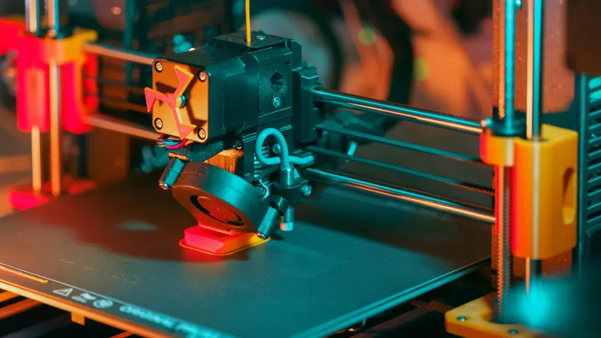
Additive tools build real 3D items from CAD. You layer raw materials slowly. Factories use Printing Technologies now. They build hard shapes without extra tools.
You push plastic wire into a hot nozzle. The hot tip melts plastic wire fast. You move the print head on X-Y paths. The nozzle drops soft plastic on a plate. The plastic cools down quickly. It turns hard fast. The build plate moves down on the Z-axis. The tool stacks new layers to finish.
Extrusion Tip: Keep nozzle heat steady. Bad heat makes weak layer bonds.
You push wet ink through small nozzles. Air pumps supply steady force. You lay fluid inks with zero heat. Air or UV light hardens paste lines. Engineers print hydrogels and clay pastes this way.
You fill a tub with liquid resin. UV light turns liquid resin hard fast. A UV laser traces your 3D design. Mirrors point the laser spot on liquid. The plate drops down after each layer.
Digital Light Processing uses a screen projector. You flash a whole 2D layer image.
SLA Resolution Scalability: System build size stays separate from print clear quality.
DLP Trade-Off: Quality depends on projector pixels. Closer screens shrink the build space.
Feature | Stereolithography (SLA) | Digital Light Processing (DLP) |
|---|---|---|
Curing Mechanism | Traces paths point-by-point using a UV laser beam | Flashes an entire 2D layer image simultaneously via a projector |
Feature Resolution | High fine XY resolution (<100 μm) with ultra-smooth interpolated curves; build volume is independent of resolution | Pixel-based resolution defined by voxel sizes; direct trade-off between print resolution and build volume |
Curing Speed | Generally slower because the laser must trace each feature individually | Faster print speeds for many parts due to single-flash full-layer curing |
You spread thin polymer powder in a box. A laser heats powder spots to melt them. You do not need extra solid supports. Loose powder holds up hanging parts easily.
Polymer powder systems mix 30 percent new powder with old powder for builds.
Adding 30 percent new powder stops material heat damage over time.
Multi Jet Fusion uses ink arrays and lamps. You spread plastic powder on hot beds. Ink sprays on exact part spots. Outer edge agents keep lines clean. Strong heat sweeps over the powder bed. Hot spots melt while plain powder stays cool.
Nozzles spray tiny liquid drops fast. The process uses high precision. These tools act like office printers. However, they build solid 3D items. They drop liquid across a plate. Parts grow layer by layer.
Heads spray liquid resin onto trays. People call this PolyJet or MultiJet. Print heads move along X-Y paths. They drop thin photopolymer resin layers. Layers measure 16 microns thin. UV light bulbs follow the head. The light cures liquid resin fast. Polymers cross-link into hard plastic instantly.
[Print Head Jets Resin Drops] ➔ [UV Light Passes Over] ➔ [Liquid Hardens Instantly]
You can run multiple print heads. This lets you mix different resins. You blend stiff and soft plastics. You also add full-color inks easily. You make realistic visual model parts.
Key Advantage: Material jetting creates super smooth surfaces. Parts match injection-molded plastic smooth quality. You need no extra post-processing.
You must build temporary gel supports. Special gel dissolves in water easily. Water jets wash the gel away.
Binder jetting uses liquids and powders. You start with dry powder beds. Metals, sands, or ceramics work well. Rollers spread paper-thin powder layers. Inkjet heads sweep across beds. Heads drop liquid glue on shapes.
Process Step | Operational Action |
|---|---|
1. Powder Layering | A counter-rotating roller spreads fine powder smoothly over the build plate. |
2. Selective Jetting | Inkjet nozzles drop liquid adhesive onto targeted powder areas. |
3. Curing Pass | An overhead heater dries the liquid glue to bind the current layer. |
4. Z-Axis Drop | The build platform drops down, ready for the next fresh layer of powder. |
You never melt powder during builds. Binder glues powder particles at room heat. Cold steps stop thermal heat stress. This stops heat warp defects too. Loose powder holds up hanging parts. You need no extra support structures.
You remove glued parts from powder. Experts call this a green part. Green parts stay weak and fragile. You bake metal parts in furnaces. Heat burns glue and fuses metal. This step makes strong metal parts.
Factories turn digital models into real plastic parts. You pick specific methods to meet your strength goals. Plastic builds use three main setups. These are nozzles, resin tubs, and powder beds. Heat or light changes these plastic items fast.
Fused Deposition Modeling melts long plastic wire. You push hard plastic into a hot tip. A drive gear pushes the wire inside. The plastic melts into soft goo quickly. The hot nozzle drops soft goo down flat. The nozzle moves along set computer paths. Soft plastic cools down and bonds fast. You stack thin layers to build solid items.
You use strong factory plastics in FDM tools. Plain PLA works well for quick tests. Hard jobs need tough plastic materials:
Acrylonitrile Butadiene Styrene (ABS): Pick ABS for tough, high-impact parts.
Polycarbonate (PC): Pick PC for super strong, heat-proof parts.
Polyether Ether Ketone (PEEK): Use PEEK for tough jobs with strong chemicals.
Polyethylene Terephthalate Glycol (PETG): Pick PETG for bendy strength and wet protection.
These materials give real factory part strength.
FDM parts show different strength across directions. Your printed item stays weaker between layers. The layer bonds stay weaker than plastic strands. Pulling layers up along the Z-axis causes breaks.
You change part strength by setting key printer values:
Nozzle Temperature: Higher heat makes layers stick much better.
Feed Rate: High speeds weaken bonds and cut strength.
Layer Thickness: Thickness shapes part strength and look.
Raster Angle: Angle sets print strength direction paths.
Build Orientation: Stacking changes how loads affect parts.
Infill Pattern and Infill Density: Internal shapes set full part strength.
Design Tip: Turn parts so forces run along horizontal X-Y paths.
Resin systems change wet liquid into solid parts. You store clear liquid resin inside tubs. Tiny monomers and short oligomers fill this resin. Light-reactive photoinitiator chemical liquids join the mix.
[Liquid Monomers & Photoinitiators] ➔ [UV Light Exposure] ➔ [Cross-Linked Solid Polymer Network]
You shine UV light rays on liquid spots. The UV light wakes up photoinitiator chemicals. Monomers lock into solid web shapes fast. This reaction turns wet resin into hard plastic.
Resin systems make super smooth part surfaces. Lasers paint detailed light lines on resin. The light builds paper-thin 25-micron layers.
Thin layers hide rough stair-step lines well. You craft smooth mold patterns for real casting. You print clear glass lenses and smooth teeth.
Powder tools use plastic dust to build parts. You spread thin nylon dust across hot boxes. PA12 and PA11 dust work best.
A strong laser hits the dust bed. The laser melts nylon dust spots together fast. Dust grains lock into hard solid parts. Loose dust stays inside the box bed. Free dust holds up your printed shapes well. You build complex shapes without support legs.
MJF and SLS make strong parts all over. Both tools melt plastic dust grains completely. This action locks layers into solid parts.
Check this data table for key strength values:
Metric | MJF PA 12 | SLS PA 650 | SLS PA 850 |
|---|---|---|---|
Tensile Strength | 49 MPa (7.1 ksi) | 1999 MPa (290 ksi) | 51.7 MPa (7.5 ksi) |
Elongation at Break | 21% | 11% | 30% |
Heat Deflection Temperature | 175°C (347°F) | 177°C (351°F) | 188°C (370°F) |
Powder tools show clear strength and visual traits:
SLS and MJF give equal strength everywhere.
SLS parts beat MJF parts in overall strength.
MJF parts offer much smoother surfaces than SLS.
Pick powder tools to make final factory parts. These solid parts handle heavy loads easily.
Metal printing changes how we make strong metal parts. You build solid parts from 3D designs. These new ways replace old casting methods. You skip hard tools and save materials.
DMLS uses strong lasers to melt metal dust. You spread metal powder inside a box. A blade makes thin layers of powder.
[Metal Powder Coating] ➔ [Laser Melts Pattern] ➔ [Build Plate Drops] ➔ [Repeat Layer]
You fill the chamber with safe gas. The gas stops rust while metal melts. A laser traces your design on powder. Heat melts metal dust into solid layers. The plate drops for new powder layers.
Thermal Stress Control: High heat creates strong internal stress. You attach metal supports to the plate. These anchors stop parts from warping.
DMLS uses tough metals that resist heat. You print shapes using top superalloys:
Inconel 718: Pick this alloy for hot jet engines.
Titanium (Ti-6Al-4V): Pick this light metal for bone implants.
Stainless Steel 316L: Pick this metal to stop rust.
Cobalt-Chrome: Pick this strong material for dental crowns.
Superalloy Class | Tensile Strength (MPa) | Thermal Resistance Limit | Key Industry Applications |
|---|---|---|---|
Inconel 718 | 1,350 - 1,400 | Up to 700°C (1,292°F) | Rocket Nozzles, Turbine Blades |
Titanium Ti64 | 900 - 1,050 | Up to 400°C (752°F) | Aerospace Structures, Bone Implants |
Cobalt-Chrome | 950 - 1,200 | Up to 600°C (1,112°F) | Dental Restorations, Joint Replacements |
Metal Binder Jetting keeps heat and shaping apart. You spread dry metal dust at room heat. An inkjet printer drops glue on powder.
You build weak metal parts without laser heat. This cold way stops all heat warp. Experts call glued parts green parts. Green parts stay very weak and soft. Touch green parts gently when cleaning dust away.
ℹ️ Cold Deposition Advantage: Binder jetting causes zero heat warp here. You pack many small parts together easily.
You bake soft green parts in two steps:
Chemical or Thermal Debinding: Warm ovens burn off liquid glue binders.
High-Temperature Sintering: Hot furnaces melt metal grains together closely.
[Fragile Green Part] ➔ [Debinding Furnace Removes Glue] ➔ [Sintering Furnace Fuses Metal] ➔ [Dense Final Metal Part]
Heat fuses metal grains into dense parts. The part shrinks up to 20 percent. Make 3D CAD models larger to fit. Final parts reach high 98 percent density.
DED uses a robot arm with nozzles. You do not use powder boxes here. A laser melts spots on real parts.
The nozzle feeds wire into laser beams. Added metal melts and bonds right away.
Powder-Fed Systems: Get fine detail and smooth material blends.
Wire-Fed Systems: Get fast builds and cheap wire costs.
DED fixes expensive worn metal parts quickly. Do not trash broken engine parts now. Mount worn parts on rotary tables instead.
[3D Scan Damaged Area] ➔ [Toolpath Generation] ➔ [DED Deposits New Metal] ➔ [CNC Machining to Final Size]
Laser scanners measure worn part spots first. Computers make paths over bad spots next. Robot arms add fresh metal layer by layer. CNC tools mill new metal to size. This fixes high-cost jet parts for cheap.
Raw 3D prints look rough. They have tiny holes. Parts hold heat stress inside. You must clean raw prints. This step makes tough parts. You smooth parts first. Then you fill open gaps. Next, you remove inner stress. Last, you add shield layers.
Media blasting shoots tiny grains. High air pressure moves them. Glass beads knock powder away. Fine sand cleans parts fast. Ceramic grit clears rough spots. This step hides layer lines.
Surface Cleanup: Sandblasting cleans hard pockets easily. It makes a smooth texture.
DMLS metal tools shine fast. Surface roughness drops low. Tests show lower roughness numbers. Parts get 80 percent smoother.
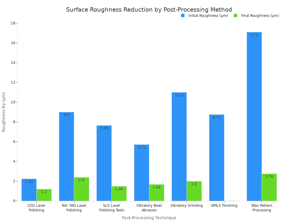
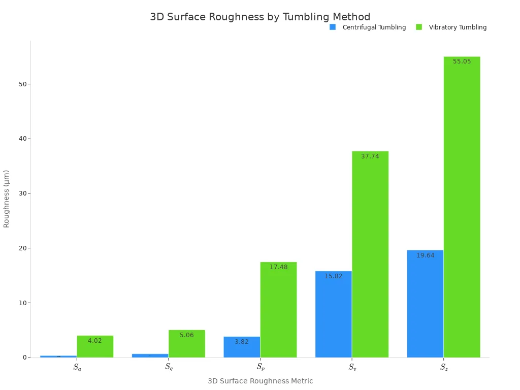
You put parts in tubs. Plastic beads fill the space. Fast spinning rubs media around. This trick shines many items. You save manual labor costs.
Tumbling Process | 3D Average Roughness ($S_a$) | Peak Height ($S_p$) | Total Height Difference ($S_z$) |
|---|---|---|---|
Centrifugal Tumbling | 0.35 µm | 3.82 µm | 19.64 µm |
Vibratory Tumbling | 4.02 µm | 17.48 µm | 55.05 µm |
Spinning tubs work super fast. They beat slow vibrating bowls.
Warm gas melts plastic coats. You hang parts inside boxes. Gas fills the room fast. Liquid vapor seals tiny gaps.
Absolute Surface Sealing: Gas seals open holes fast. Water cannot leak through.
Micro-Crack Reduction: Melting removes weak surface spots. Nylon parts bend much better.
Fatigue Life Improvement: Smooth plastic stops deep cracks. Parts handle heavy loads well.
Metal prints trap inner heat. Laser heat locks tension inside. You bake parts in ovens. Hot air relaxes locked forces.
You warm plastic parts slowly. Do not melt the shapes. Next, cool parts down slowly. This step stops warp defects. Shape sizes stay very steady.
Raw prints soak up water. Clear liquid sprays shield parts. You dip parts in epoxy.
[Raw Porous Part] ➔ [Liquid Epoxy Immersion] ➔ [UV or Heat Cure] ➔ [Sealed Chemical-Resistant Part]
UV coats block sun damage. Seals hold liquid inside tanks.
Paint adds nice color coats. Paint shields raw plastic walls. You spray primer liquid first. Primer fills teeny gaps well.
Spray Painting: You spray clear acrylic paints. Paint matches custom color codes.
Powder Coating: You stick color powder onto metal. Heat bakes the powder hard.
Paint stops bad surface scratches. It guards parts against rust. Harsh weather will not hurt.
Additive tools change modern production lines. You build complex custom parts fast. Factories swap huge warehouses for computer files.
Smart software designs light airframe parts. Computer tools strip away extra metal. They place metal only along force lines.
Weight Reduction: Inner lattice shapes drop part weight. Lighter planes burn much less fuel.
Rocket engines need heat-proof metal parts. You print combustion chambers with Inconel. Lasers build curved inner cooling paths. Old drills cannot cut curved holes inside.
Car lines need custom clamps fast. You print hard plastic tools quickly.
Initial Investment Payback: Print tools pay for themselves fast.
Enterprise Case Example: Volkswagen saved €475,000 using printed tools.
Break-Even Volume: Shops profit after printing 37 tools.
Impact Category | Quantitative Metric | Operational Benefit |
|---|---|---|
Tooling Expense | 70% decrease | Lowers total tool costs |
Tool Delivery Speed | 90% acceleration | Cuts build times fast |
Inventory Expenses | 75% drop in spare parts | Drops storage costs easily |
Car makers save computer CAD files. You print rare replacement parts fast. Digital storage cuts big physical shop costs.
Doctors design titanium bones from scans. UK surgical studies praise these custom implants.
Implant Type | Adaptation Method | Clinical Efficacy & Accuracy Findings |
|---|---|---|
Patient-Specific 3D Titanium | Fits natural bone curves well | Gives exact fit and cuts time |
Off-the-Shelf Plates | Needs manual bending by hand | Fits poorly and weakens parts |
Dentists print clear resin drill guides. Guides snap right onto teeth. They hold drills at safe angles.
markdown
Picking factory tools needs clear checks. You compare money, time, and materials. Compare old ways and 3D choices.
Every build project relies on total costs. Check job time lines too. Check run sizes first. This matches your set budget.
Old ways need costly metal plates first. Custom steel dies cost big money. Single items cost too much here. Unit costs drop on big runs. You print thousands of matching items fast. Big runs split high initial setup costs.
Additive systems skip real metal tools completely. Send a digital CAD file right away. Making one part costs the same. Making fifty parts costs the same too. Small jobs pick additive options easily. You skip heavy upfront tooling bills.
Production Factor | Additive Manufacturing | Traditional Printing |
|---|---|---|
Initial Setup Cost | Very Low | Very High |
Unit Cost (Low Volume) | Low | High |
Unit Cost (High Volume) | High | Extremely Low |
Production Flexibility | Instant Changes | Hard Tooling Changes |
Steel molds take long wait times. Gravure cylinders take weeks to make. Machining metal tools takes many months. Late design tweaks ruin your schedule. Last-minute changes drain your funds fast.
Additive tools print solid parts quickly. Jobs finish inside a few hours. Update digital model files right away. Restart the machine to build parts. This fast speed cuts bad delays. You launch new products much faster.
Selection Rule: Pick additive methods for small jobs. Use traditional tools for huge runs.
Strong mechanical goals limit your choices. Map out key load forces first. Check heat limits and look needs.
Engineers test heavy load limits today. They test hot factory rooms too. Powder systems make dense, hard items. Metal laser tools give high strength. Parts match old forged metal tools.
[Define Mechanical Load] ➔ [Check Heat Limits] ➔ [Select Polymer or Metal System]
FDM plastic parts show lower Z-axis strength. Weak layer bonds cause this loss. Place models carefully on plates. Good spots stop layer breaks under stress.
Smooth texture sets proper part fit. Tight sizes set proper part fit. Offset presses give silky surfaces fast. Liquid photopolymer jetting hides layer lines.
SLA holds tight sizes very well.
Powder polymer tools make rougher surfaces.
Media blasting improves rough surfaces fast.
Know structural limits to grade Printing Technologies. Match part needs to make good parts.
You pick old methods for big jobs. They give low unit costs. You pick additive systems for hard shapes. They make quick models and custom designs fast. Check batch size and material strength first. Check exact size needs to choose well. Modern Printing Technologies match factory goals directly.
Future plants mix additive layers with CNC tools. These hybrid setups boost part accuracy fast. They automate surface smoothing too.
Metric | Value |
|---|---|
2025 Estimated Market Size | USD 2.91 Billion |
Projected 2035 Market Size | USD 23.63 Billion |
Forecast CAGR (2026–2035) | 23.3% |
Fastest Growing Region | Asia Pacific |
Decision Roadmap: Check your total job size first. Pick old presses for huge builds. Choose additive tools for small runs. Pick them for custom parts or quick updates.
Check total batch size and part needs. Pick traditional printing for big runs. Big runs lower single item costs. Pick additive manufacturing for fast tests. It makes custom shapes fast. It builds small jobs without costly tools.
Isotropic parts show equal strength everywhere. Anisotropic parts have weak lines. Stacking layers causes weak spots.
| Property Type | Strength Direction | Typical Process | | : | : | : | | Isotropic | Equal in all directions ($X, Y, Z$) | Powder Bed Fusion (SLS/MJF) | | Anisotropic | Weaker along $Z$-axis layers | Fused Deposition Modeling (FDM) |
Thermal Control: Lasers create extreme heat. Anchor parts to the plate. Supports pull heat away. They stop bad warp defects.
Yes, you build factory parts with nylon dust. SLS and MJF melt plastic dust grains completely. They create strong, tough parts. These parts handle heavy daily loads easily.
Glue holds metal powder in green parts. Touch these fragile parts gently. You bake parts in hot ovens. Heat burns glue away. It melts metal grains into solid parts.
Warm gas touches soft plastic parts. Gas melts the top coat slightly. This action seals tiny open gaps.
It stops liquid leaks easily.
It smooths rough layer lines.
It helps parts last longer.